
UgCS Photogrammetry tool for UAV Land Survey Missions
- David Leblanc
- Jan 27, 2023
- 12 min read
Contents
UgCS Photogrammetry tool for UAV Land surveying missions
Main UAV advantages compared to traditional survey solutions
Flight planning workflow in UgCS
Step one: Specify the desired result
Step two: import an accurate map and elevation data to UgCS (optional)
Step three: Plan the mission
Initial planning
Route validation
Altitude type
Survey line direction
Turn types
Overshoot
Camera control method
NADIR/Oblique photography
Action execution
Making a double grid
Reducing the number of waypoints during AGL flight
Speed
Take-off point
The survey grid entry point
Landing point
Step four: deploy ground control points (optional)
Step five: fly your mission
Step six: PPK processing and image geotagging (optional)
Step seven: data processing
UgCS Photogrammetry tool for UAV Land survey missions
Unmanned Aerial Vehicles (UAV) or drones revolutionize mapping services and help generate accurate orthomosaics, point clouds, and elevation models faster. Drones and cameras evolve amazingly quickly, however, the output accuracy and precision of resulting products strongly depend on the flight planning software.
Main UAV advantages compared to traditional survey solutions
Faster data acquisition. With real-time kinematic (RTK) and post-processed kinematic (PPK) technologies, there is no need to place ground control points (GCP) for many applications
UAV equipment is less expensive than traditional land survey equipment
Drones can approach areas unreachable by foot or by car
UgCS by SPH Engineering is a globally known UAV mission planning and flight control software solution. UgCS supports almost any UAV platform, provides convenient tools for areal and linear surveys, and enables direct drone control. UgCS ensures professional land survey mission planning using the photogrammetry technique.
Flight planning workflow in UgCS
Specify the desired result
Import an accurate map and elevation data to UgCS (optional)
Plan the mission
Deploy ground control points (optional)
Fly the mission
Create image geotags (optional)
Process data
Step one: Specify the desired result
Define input settings first:
Required GSD (ground sampling distance)
Survey area boundaries
Required forward and side overlap
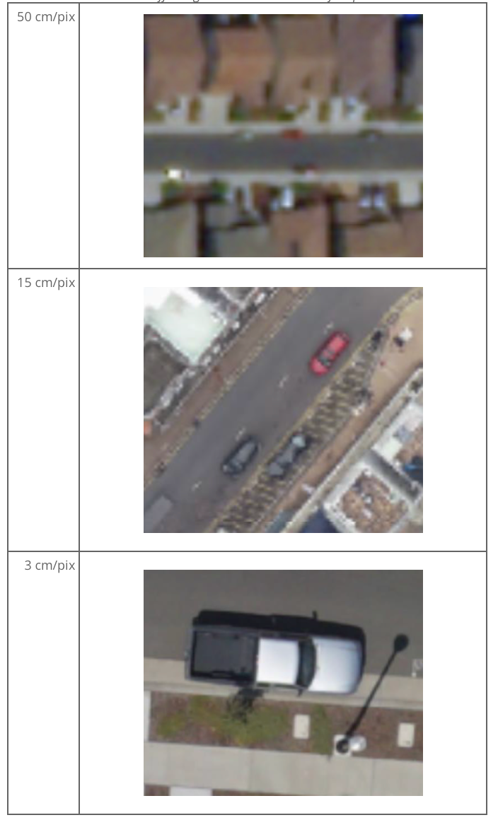
GSD is the spatial resolution of a sensor. It is the distance measured in centimeters between the centers of two neighboring pixels in the image on the ground surface. GSD and area boundaries usually are defined by desired customer output (e.g., digital map scale and resolution). GSD affects the level of detail of acquired data. Below are examples of how a car may look like in the pictures with different GSDs Table 1 GSD affecting the detalisation level of acquired data50 cm/pix15 cm/pix3 cm/pix
Pilots can either draw survey boundaries manually in UgCS or import them from a KML. The overlap should be chosen according to specific conditions of the survey area and requirements of drone data processing software.
By default, 60% forward and 30% side overlap are the minimum recommended settings. Overlap can be increased for areas with vertical surfaces or highly uniform visual surfaces (desert, snow).
Very often aerial photogrammetry newbies are excited about making a digital map with extremely high resolution (1-2 cm/pixel) and use very small GSD for mission planning. This is very bad practice, as small GSD means longer flight time, hundreds of photos for each acre, tens of hours of processing, and heavy output files. GSD should be set according to the desired digital map parameters.
Other limitations may also apply. For example, a GSD of 10 cm/pixel is required, but a drone is going to carry a Sony A7 III camera with a 24 MP sensor. To meet such GSD the drone has to fly at 510 meters above the ground. The problem is that in most countries maximum allowed UAV altitude (without special permission) is limited to 120 m/400 ft AGL (above ground level). Given the maximum allowed altitude, the highest possible GSD, in this case, could be just 2.3 cm.
Step two: import an accurate map and elevation data to UgCS (optional)
By default, UgCS provides access to a variety of online tiles services and SRTM elevation data. Pilots may also have orthomosaics and/or elevation data from surveys or satellite data providers. If that’s the case pilots can upload this data into UgCS and make more accurate flight planning.
Open Map layers to upload a map or elevation data (Figure 1).
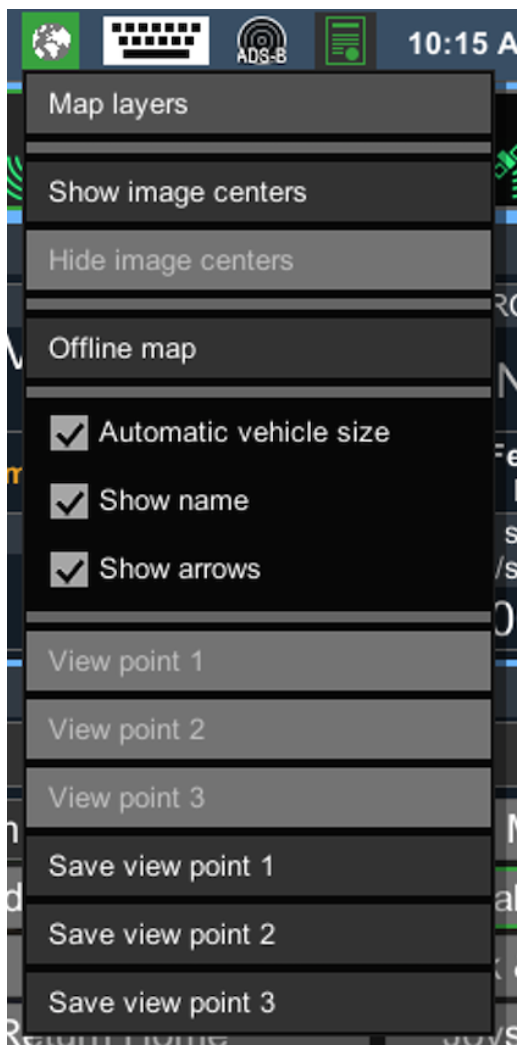
Figure 1 Open Map layers to upload a map or elevation data into UgCS
Open Map and Elevation tabs to Add new sources and Upload orthomosaics (GeoTiff) or elevation data (Figure 2).

Figure 2 Adding new sources and uploading orthomosaics (GeoTiff) or elevation data to UgCS
Video 1 Import of an accurate map and elevation data into UgCS
Initial planning
The first step is to specify your drone survey area using the Photogrammetry tool. To do it, put visual cues on an underlying map or input exact coordinates of edges. The resulting survey area is marked with yellow boundaries (Figure 3).

Figure 3 Setting survey area using UgCS Photogrammetry tool
Another option is to import area boundaries from KML: add a new route, select “Import from file”, and then select using Photogrammetry for all LineRing objects in the KML file (Figure 4).

Figure 4 Setting drone survey area by importing area boundaries from KML
Then, set GSD and overlap for the camera in the Photogrammetry tool's settings window (Figure 5).

Figure 5 Setting overlap and camera’s Ground Sampling Distance (GSD)
To take photos, set the camera control action in the Photogrammetry tool's settings window. In the example (Figure 5), Set camera by distance triggering action with default values is used.
At this point, initial route planning is completed. UgCS will automatically calculate the photogrammetry route.
However, the automatically calculated photogrammetry route is often non-optimal and sometimes even dangerous for the drone or surroundings. Therefore, go to the step “Route validation”.
Route validation
UgCS generates a trajectory that will be uploaded to the drone. Pilots can see it as a green 3D polyline and check other parameters of the calculated flight plan.
The first part of this information can be found in the Elevation profile window. To open the Elevation window (if it is invisible on the screen), click the Parameters icon on the Route card (lower-right corner, see Figure 6) and select Show elevation from the drop-down menu:

Figure 6 Accessing the Elevation window in the Parameters settings of the Route card
The Elevation profile window will display estimated route length, duration, waypoint count, and min/max altitude (Figure 7).

Figure 7 Route values in the Elevation profile window
To get other calculated values (Figure 8), open Route log by clicking on Route status indicator - the green check-mark (upper-right corner, see Figure 6) of the Route card.

Figure 8 Route card and status indicator, Route log
You can use route parameters to optimize performance and improve efficiency and safety.
Altitude type
UgCS Photogrammetry tool has the option to define route tracing method according to altitude - with constant altitude above ground (AGL) or above mean sea level (AMSL).
Please refer to your UAV data processing software requirements to see the recommended altitude tracking method.
UgCS team's experience shows that the choice of altitude type depends on the desired output. For orthophoto map (standard aerial land survey output format), it is better to choose AGL to ensure constant GSD for the entire map. For DEM or 3D reconstruction, use AMSL to provide the data processing software with more data in order to correctly determine ground elevation by photos and obtain an output of higher quality.

Figure 9 Elevation profile with constant altitude above mean sea level (AMSL)
In this case, UgCS will calculate flight altitude based on the lowest point of the survey area (Figure 9).
If AGL is selected in the Photogrammetry tool settings, UgCS will calculate altitude for each waypoint but in this case, terrain-following will be rough if no “Additional waypoints” are added (Figure 10).

Figure 10 Elevation profile with AGL without additional waypoints
Therefore, if AGL is used, add some “Additional waypoints” flags, and UgCS will calculate a flight plan in accordance with the elevation profile (Figure 11).

Figure 11 Elevation profile (AGL) and additional waypoints
Survey line direction
By default, UgCS will generate forwarded passes oriented along the longest side of the area. To change this default setting, pilots may change the Direction angle field of the Photogrammetry tool and use a rotating arrow on the polygon itself to adjust the same parameter (Figure 12, 13).

Figure 12 Direction angle = 246 degrees from North

Figure 13 Changing a survey line angle to make the line parallel to the longest boundary. New direction angle = 328 degrees from North
Turn types
Most autopilots or multirotor drones support different turn types in waypoints. DJI drones, which are one of the most popular, have two turn types (Figure 14):
Stop and Turn: drone flies to the fixed point accurately, stays at that fixed point, and then flies to the next fixed point.
Adaptive Bank Turn: the performance is similar to Bank Turn mode (Figure 14) but the real flight routine will be more accurate.
Adaptive Bank Turn should be used with caution because drones can miss waypoints and no camera triggering will be initiated.

Figure 14 Typical DJI drone trajectories for Bank Turn and Adaptive Bank Turn types
To shorten the flight time (compared to the Stop and Turn), use the Adaptive Bank Turn. Combining the Adaptive Bank Turns with Overshoot (see the Overshoot section) is recommended for the photogrammetry area.
Overshoot
Initially, overshoot was designed for fixed-wing (airplane) drones to have enough space for U-turn maneuvering.
Overshoot can be set in the Photogrammetry tool to add extra segments to both ends of each survey line.
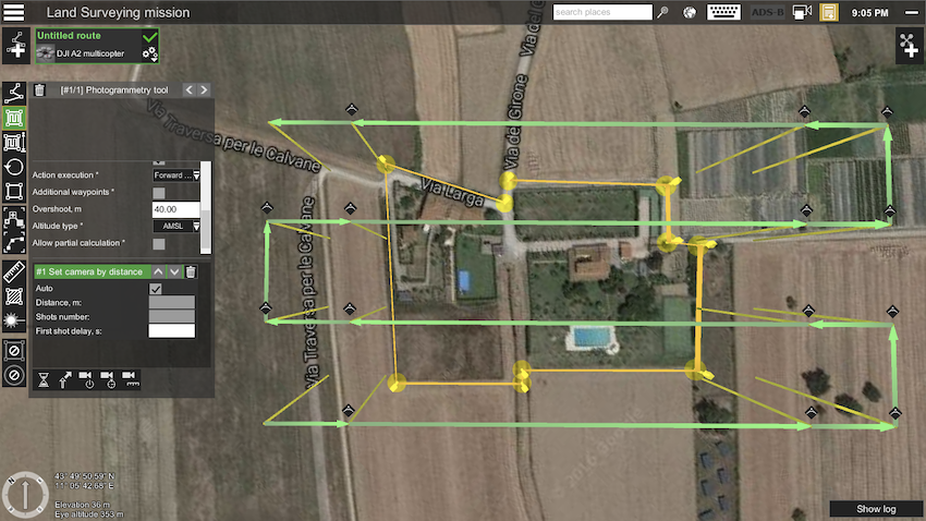
Figure 15 Adding 40 m overshoot to both ends of each survey line
Figure 15 shows that UgCS added 40 m segments to both ends of each survey line (comparing to Figure 13).
Adding the overshoot for copter UAVs is useful in two situations:
When Adaptive Bank Turns are used (or a similar method for non-DJI drones), adding the overshoot will increase the chance that the drone will precisely enter the survey line and camera control action will be triggered. UgCS team recommends setting the overshoot to be approximately equal to the distance between parallel survey lines.
When Stop and Turn type is combined with camera triggering in waypoints, there is a risk that before making the shot, the drone will start rotation to the next waypoint, thus bringing back wrongly oriented or blurred photos (Figure 16). To avoid that, set shorter overshoot, for example, 5 m. Don’t set too short a value (< 3 m) because some drones can ignore waypoints that are too close.

Figure 16 Example of a blurred image taken by a drone in a rotation to the next waypoint
Camera control method
UgCS supports three camera control actions:
“Set camera mode” to make the shot exactly in a specified point
“Set camera by the time” to make shots every N seconds
“Set camera by distance” to make shots every N meters
Here are some benefits and drawbacks of all three methods:

NADIR/Oblique photography
In most cases for a photogrammetry survey camera shall look straight down. Please make sure that the “Set camera” attitude action with a 90-degree tilt angle is selected for the photogrammetry segment (Figure 17).

Figure 17 Setting the camera's attitude and position with a 90-degree tilt angle
For urban areas with vertical surfaces, we recommend making another pass over the areas with the camera tilted at 45 degrees (Figure 18). This will enable to capture of the walls and increase the quality of the point cloud.

Figure 18 Setting the camera's attitude and position with a 45-degree tilt angle
As described above, this waypoint should be set as Stop&Turn type, otherwise, the drone may skip this action. To set the camera to a horizontal position, select the last survey route waypoint, click Set camera attitude/zoom, and enter "0" in the "Tilt" field.
Action execution
The photogrammetry tool has an advanced Action Execution parameter with three possible values:
Every point
At start
Forward passes
This parameter defines how and where camera actions specified for the Photogrammetry tool will be executed.
The most useful option for photogrammetry/survey missions is to set Forward passes: a drone will only take photos on survey lines and will not take excess photos on perpendicular lines.
Complex survey areas
Sometimes, a photogrammetry/survey mission has to be planned for irregular areas. For example, if two fields connected in a “T” shape are marked as a single photogrammetry area, the route will not be optimal, regardless of any survey line direction (Figure 19).

Figure 19 Complex survey area before optimization
UgCS functionality makes it possible to combine any number of photogrammetry areas in one route and avoid splitting the area into separate routes. Survey lines for each area can be optimized individually (Figure 20).UgCS functionality makes it possible to combine any number of photogrammetry areas in one route and avoid splitting the area into separate routes. Survey lines for each area can be optimized individually (Figure 20).

Figure 20 Optimized survey flight passes for each part of a complex photogrammetry area
Making a double grid
Double grid is a very efficient way of increasing the point cloud quality in urban areas and areas with complex elevation or high vegetation. Use Double grid option in photogrammetry settings (Figure 21).

Figure 21 Double grid option enabled in photogrammetry settings
Reducing the number of waypoints during AGL flight
Flying at a constant altitude above the ground will lead to excessive waypoints. The autopilot can support a limited quantity of waypoints, so a pilot may want to reduce this number. Reducing the trajectory level of details will also result in smoother drone movements (compare Figure 22 and Figure 23). AGL tolerance parameter of the photogrammetry survey can be used for AGL altitude mode. AGL tolerance specifies vertical corridor. As long as the trajectory is within the upper and lower limits of this corridor, no additional points are generated by UgCS.

Figure 22 AGL Tolerance = 2 m

Figure 23 AGL Tolerance = 10 m
Speed
Generally, the higher the flight speed, the shorter the flight time is. But high speed in combination with large camera exposure can result in blurred images. In most cases, 10 m/s is the best choice.
Take-off point
It is important to check the take-off area at the site before flying any mission! To better explain the best practice of setting a Take-off point, let's first review an example of how it should not be done. The take-off point in the example mission (Figure 24) is marked with an airplane icon, and a drone pilot will upload the route on the ground by setting an Automatic mission for automatic take-off.

Figure 24 Take-off point example
Most drones in automatic take-off mode would climb to a low altitude of about 3-10 meters and then fly straight towards the first waypoint. Other drones would fly towards the first waypoint straight from the ground. At the example map (Figure 24), some trees between the take-off point and the first waypoint can be noticed. In this example, the drone more likely will not reach safe altitude and will hit the trees.
Not only the surroundings can affect Take-off planning. Drone manufacturers may change elevation behavior in drone firmware: therefore, it is recommended to check the drone's automatic take-off mode after firmware updates.
Remember that most small UAVs use relative altitude for mission planning. Altitude counting based on the first waypoint is the second reason why the actual take-off point should be near the first waypoint and on the same terrain level.
UgCS team recommends placing the first waypoint as close to the actual take-off point as possible and specify safe take-off altitude (~30 m will be above any trees in most situations, see Figure 25). This is the only way to guarantee safe take-off for any mission and keep safe from any weird drone behavior, unpredictable firmware updates, etc.

Figure 25 Route with safe take-off
The survey grid entry point
Adding the take-off point has changed the survey grid entry point, thus optimizing the entire route (see Figure 25).
To change the survey grid entry point, set an additional waypoint close to the desired starting corner (Figure 26).

Figure 26 Changing survey grid entry point by adding a waypoint
Landing point
If no landing point is added outside the photogrammetry area then, after the survey mission, the drone will fly and hover in the last waypoint. There are two landing options:
Take manual control over the drone and direct it to the landing point
Activate the Return Home command in UgCS or from Remote Controller (RC)
A large survey area or problems with Remote Controller may result in losing radio contact with a drone. In this case, the following scenarios can take place depending on the drone and its settings:
A drone will return to the home location automatically if the radio link with the ground station is lost
A drone will fly to the last waypoint and hover. If the battery charge is sufficient then:
the drone will perform an emergency landing or
the drone will try to fly to the home location
It is recommend adding an explicit landing point to the route to avoid relying on unpredictable drone behavior or settings.
A last waypoint should be added over the planned landing point if the drone doesn’t support automatic landing or the pilot prefers manual landing. The altitude of the last waypoint should be set above obstacles in the surrounding area to ensure safe descending and comfortable landing. In general, 30 m is the best choice.
Step four: deploy ground control points (optional)
This step used to be mandatory in order to precisely align a survey output map with coordinates on Earth. Now, it’s up to the pilot and the customer whether to deploy ground control points or use just PPK. However, the usage of GCP is still the only way to ensure map accuracy.
Agisoft Metashape, Pix4d, and other data processing software can produce accurate maps using geotagged images, but anyway require ground control points to achieve true precision.
Ground control points should be used for Survey-Grade output. To obtain a map with “good enough” precision, just RTK GPS and data processing software capabilities are okay.
Step five: fly your mission
In case of a carefully planned mission, this step is truly straightforward. Mission execution will not be described here, as it may vary depending on the type of UAV and equipment in use (please refer to equipment and UgCS Manuals). Important notes before flying:
Most countries have more or less strict UAV-related regulations, usually available on a local aviation authority’s website.
In some countries a special permission for any kind of aerial photo/video shooting is required. Please check local regulations (fines and other consequences can be costly).
Even if mission planning seems to be done with excellence always double-check it when coming on site, considering specifics of a particular survey area and local flying conditions.
Step six: PPK processing and image geotagging (optional)
Image geotagging is optional for modern drones. It can be done either automatically during the flight, or in UgCS after drone landing.
Mind that PPK processing is enough in most cases. Use your favorite tool, like this.
However, only ground control points ensure the desired map accuracy.
Step seven: data processing
For data processing, use third-party software or services available on the market. For fast processing in the field, UgCS Mapper, is a good option as it works without an internet connection. For flight fidelity processing, use Pix4D Mapper, Agisoft Metashape, or other professional tools, which support dense point cloud generations and GCPs.


Comments